
Steel Grating Panel Layout Guide: Direction, Supports and Cut-Outs
A correct panel layout starts with the support steel. Bearing bars span between supports; panel joints, cut-outs, banding, and piece marks are then coordinated around that load path.
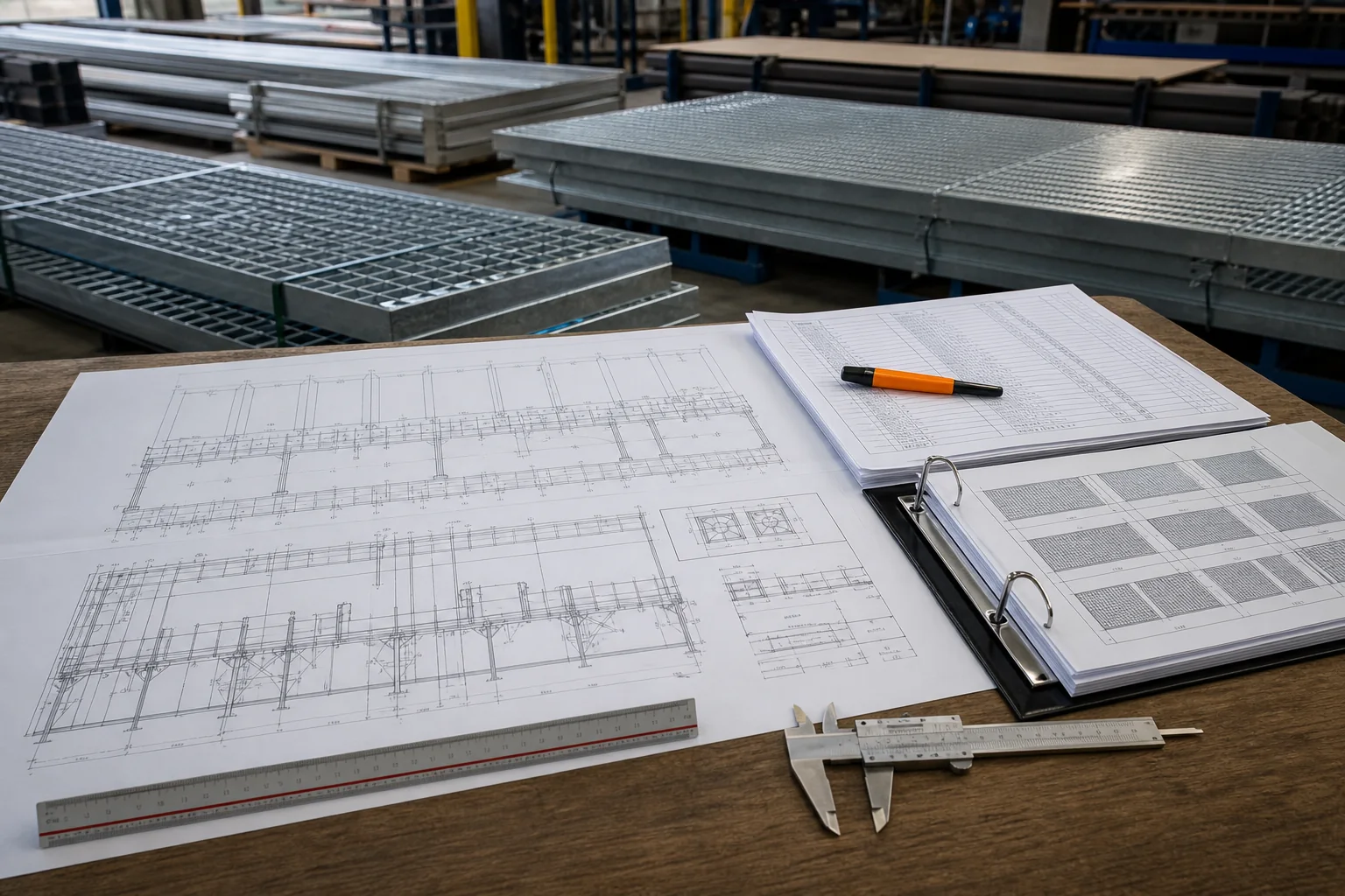
What controls a steel grating panel layout?
The structural support arrangement controls the layout. First mark beams, channels, angles, and other bearing seats. Then identify the clear span between them. The grating bearing bars must run across that span and rest on support at both ends.
Cross bars keep bearing bars aligned and distribute local effects, but they are not the primary spanning members. Reversing the panel because it fits the opening more neatly can therefore create an unsafe load path.
Step 1: mark supports and bearing-bar direction
On the general arrangement drawing, use arrows to show bearing-bar direction in every platform zone. State the clear span and required bearing length. Where support information is missing, label it for clarification instead of assuming the panel can span in either direction.
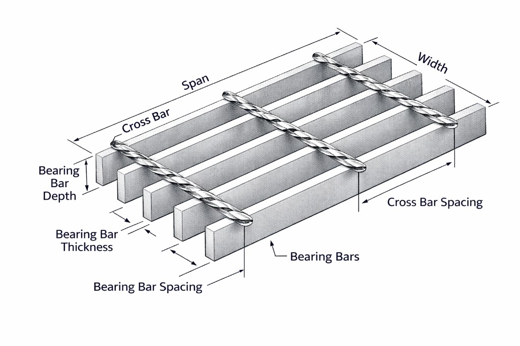
Step 2: place panel joints over support steel
Panel ends should normally bear on structural steel. A joint located in an unsupported opening leaves the bearing-bar ends without a load path. If two panels must meet away from a beam, the connection needs a project-specific engineered detail.
Use practical panel sizes that can be galvanized, transported, lifted, and installed. Very large panels may reduce joint count but increase handling risk. Very small panels add banding, fixings, fabrication time, and site labor.
Step 3: coordinate cut-outs and edge treatment
Show pipes, columns, ducts, equipment bases, drains, and access openings with dimensions from fixed grid lines. Identify whether each opening is shop-cut or field-cut. Shop-cut edges should state the required banding, toe plate, or kick plate detail.
Where equipment dimensions may change, a removable rectangular panel is often easier to manage than several irregular pieces. The final solution must still preserve support and safe access around the opening.
Step 4: assign piece marks and installation zones
Every unique fabricated shape needs a piece mark. Use the same mark on the panel layout, BOM, production label, packing list, and installation drawing. Add area, elevation, or grid reference so panels can be bundled in installation sequence.
Repeated rectangular panels may share a mark only when dimensions, grating specification, finish, banding, and all fabrication details are identical.
Step 5: specify tolerances, fixings, and removable panels
- State the project drawing tolerance and any critical interface dimensions.
- Identify fixed and removable panels.
- Show clip type and fixing zones; see Installation & Fixings.
- State material, surface profile, and finish.
- Check doors, handrails, ladders, pipework, and maintenance routes for clashes.
Panel layout release checklist
- Latest structural drawing and revision confirmed.
- Support lines, clear spans, and bearing-bar arrows shown.
- Panel boundaries and piece marks coordinated with the BOM.
- All cut-outs, banding, toe plates, nosing, and removable zones defined.
- Panel sizes checked for fabrication, finish, transport, lifting, and installation.
- Open technical questions recorded before production release.
Frequently asked questions
Which direction should steel grating bearing bars run?
Bearing bars must span directly between structural supports. Their direction is perpendicular to the support lines that carry the panel.
Can two grating panels meet without support below the joint?
Normally no. Each load-carrying panel edge needs adequate bearing unless a specifically engineered joint detail is provided.
What should I send for a panel-layout review?
Send the latest GA drawing, support-steel plan, sections, grating specification, openings, finish, and any existing BOM. Upload the drawing package for takeoff and layout review.